Your shopping cart is empty!

MENU
Your shopping cart is empty!
This project builds upon our previous Stage 1 GTT Thermometer demo. We've implemented 4 additional buttons, and 2 dynamic labels to create an interactive HMI for setting high and low temperature limits. The Arduino will continually take readings and update the GTT's bar graph and label. If the temperature exceeds either of the two limits, the GTT's piezo buzzer and feedback motor will be activated to alert the user.
Hardware
Software
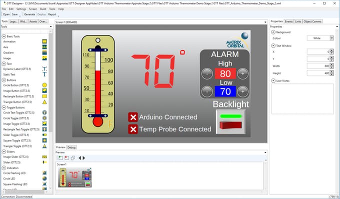
Step 1: Designing the User Interface
Our previous GTT Designer project was modified for this demo. Two labels are implemented to display the high and low temperature limits. Four buttons add control, allowing users to manually set the high and low temperature limits. Each button label has been changed to a '+' or '-' to indicate their function appropriately.
The bar graph, indicator toggles, and current temperature label that were implemented in the previous stage are still present here.
You can download our free and fast GUI design software here.
The project files can be downloaded here.
GTT Designer GUI Software
Once the design is completed, the project can be deployed to the GTT. You'll need to connect your PC to the GTT's Mass Storage header, and hit "Deploy" in the GTT Designer. All the necessary files will be generated and deployed directly to the display.
Step 2: Connecting the GTT
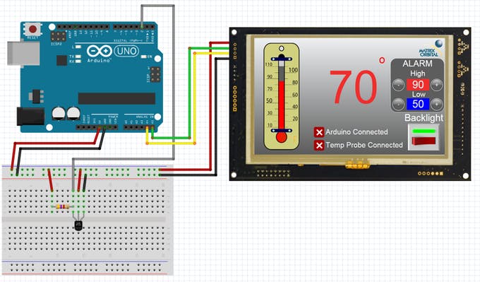
Similar to our Stage 1 demo, we'll continue to use I2C to communicate between the Arduino Uno and the GTT. Using the Bread Board Cable, connect the 4 pin header to the GTT's I2C header. Then connect the Red Bread Board Cable lead to 5V power, and connect the Black lead to ground. The Yellow (SDA) and Green (SCL) leads need to be connected to the Arduino Uno's SDA pin (A4) and SCL pin (A5) respectively. No I2C pull-up resistors are required for communication with the GTT. Additional power can be applied through the displays barrel jack.
Step 3: Connecting the DS18S20
A 4.7k Ohm pull-up resistor must be placed in parallel with the D18S20's power and data pins, otherwise the sensor will be unable to communicate properly. The data pin can be connected to any digital pin on the Arduino; in this case we selected pin 2.
Step 4: Installing Libraries
Before continuing, download and unzip the the following GTT Client Libraries. These libraries can also be found within the most recent GTT Firmware release. Once downloaded, copy over the contents of GttClient into \Users\YourUserName\Documents\Arduino\libraries\gtt. GTT Client Library
The OneWire library will also be required for this demo. You can install the OneWire library through the Aduino IDE Library Manager.
Step 5: Code
Download the GTT_Arduino_Thermometer_Demo.ino file. Navigate to the GTT Arduino Thermometer Demo Stage 2 GTT files>Output folder, and grab the.c and.h files generated by the GTT Designer Suite. Place both files in the GTT_Arduino_Thermometer_Demo_Stage_2.ino source directory, then open the.ino file.
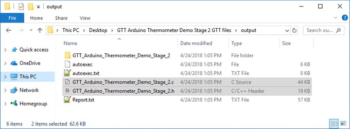
GTT Designer generated .c and .h files
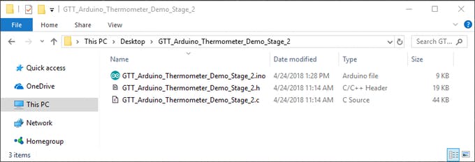
.c and .h file in the Demo Source directory
If everything is setup properly, the.c and.h file will open along with the GTT_Arduino_Thermometer_Demo.ino code.From there, you can upload the program to the Uno. The GTT will reset immediately after the program is uploaded. After a few seconds, the Thermometer demo screen will be displayed on the GTT. The image toggles will be set, indicating the connection status of the Arduino and the DS18S20 probe. If the probe becomes disconnected at any point, the indicators will provide visual notification that no temperature probe can be found.
The high and low limits default to 90°f and 60°f respectively. The high and low limits can be manually set by the operator by pressing the '+' and '-' buttons.


